Prelab
Wiring
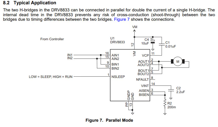
I am going to use the guide provided by the TI datasheet to wire up my car. This is what I found in the documentation and will be my general wiring scheme.
I am ensuring all of my pins are PWM capable. I am finding if pins are PWM capable by looking at the schematic and I learned from Aidan that a tilde next to a pin means that it is PWM capable. I chose to use A0, A1, A2, and A3 to connect my motor drivers in because that works best with my orientation of my Artemis.
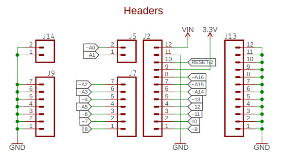
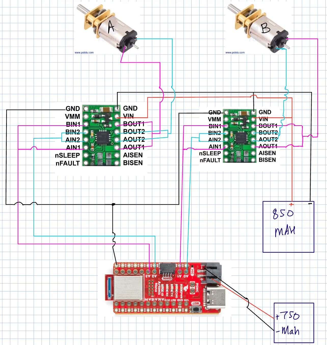
I wanted to have my USB port on the right side of my car so I chose to use the pins that are closest to that side of the board. I have attached my wiring diagram below. The use of these pins will also decrease the length of my runs and allow me to size my wires properly.
Power
I think that we are using different batteries for the Artemis and the motors so that any back EMF or the high current spikes as power is drawn by the motor doesn't burn out the Artemis. I also think that 2 batteries are used so that the battery life of the robot can be longer while still maintaining a small compact battery since the motor can draw from the higher energy battery pack and the artemis can operate independently. Another reason is that since the motors draw a lot of power that will make the motor battery run out of power faster and that might result in the Artemis not getting enough current or voltage which could damage it as well.
Lab Tasks
Soldering and Wiring
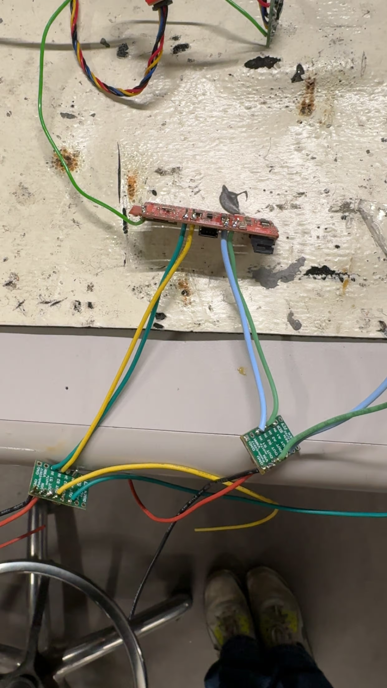
Here I soldered and wired the device as I showed in my wiring diagram above. Here is a picture showing how it looks after it has been all soldered with my Artemis.
Testing PWM
Analog Write Code
Here is the code that I used to test the PWM of the motor drivers. I used a small delay between the on and off to simulate some power modulation.
Pin Setup:
const int Drive1AB1 = 1;
const int Drive1AB2 = 0;
const int Drive2AB1 = 3;
const int Drive2AB2 = 2;

pinMode(Drive2AB1,OUTPUT);
pinMode(Drive2AB2,OUTPUT);
Loop:
  analogWrite(Drive2AB1, 127); //255 is full duty cycle so using 127 for 50%
  analogWrite(Drive2AB2, 0);
Power Supply Settings
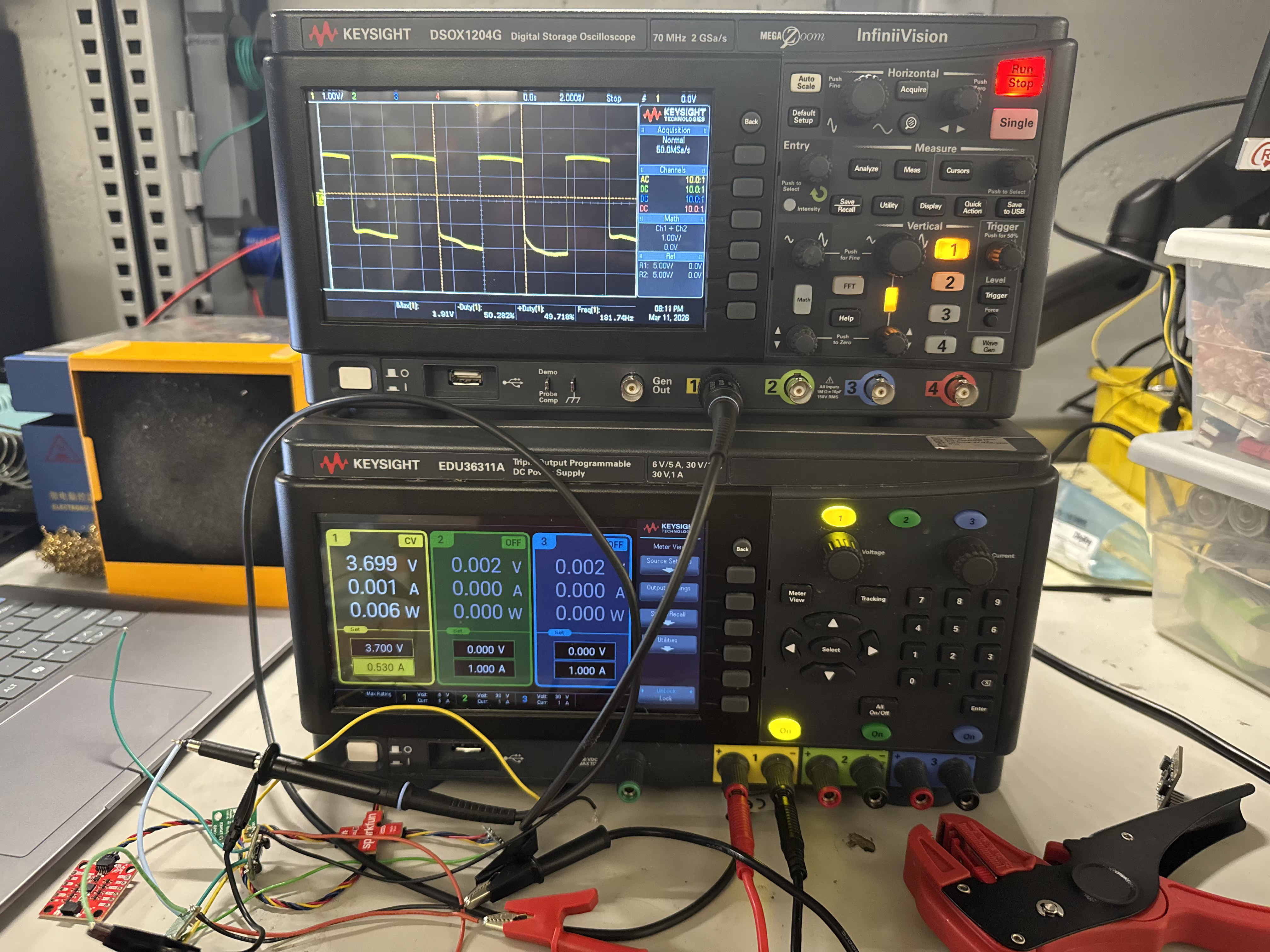
For the power supply I wanted to emulate the battery as close as I could, and since the battery is a 3.7V cell, I set the power supply to a voltage of 3.7V. I let it be voltage limited and let it draw current as it needed but set a maximum of 0.5A to ensure that nothing would burn out. I found that this worked well and the power draw was only roughly 1 mA and it was voltage limited as I predicted.
Ossciliscope Setup and Results
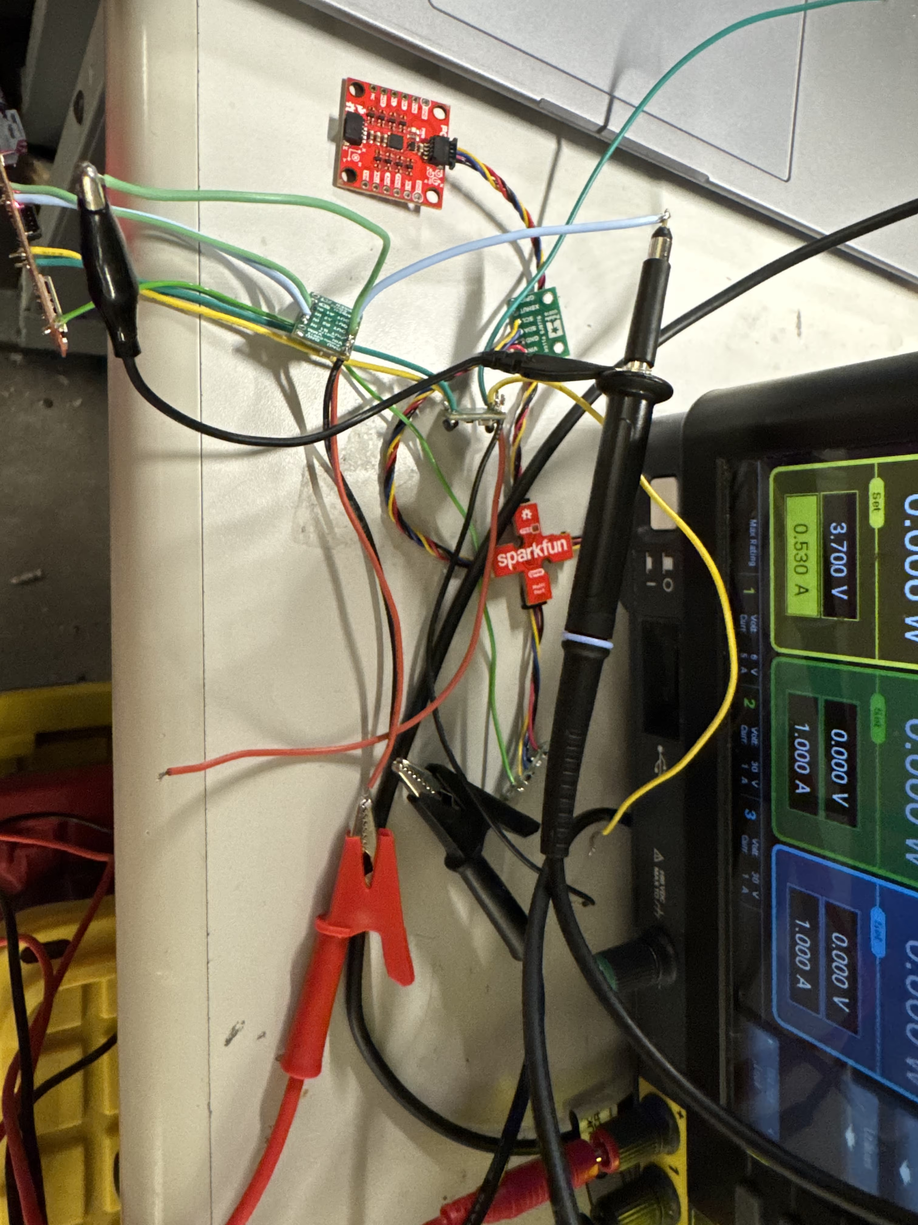
I set up my power supply such that it was supplying ground to the ground on the motor controller, and the positive was connected to Vin. For the ossciliscope I set the ground alligator clip on the probe to the output that has a 0 duty cycle, and I set the probe on the one that I applied the 50% duty cycle analogWrite too. One issue I found is that the off part of the duty cycle kept moving a little bit, I think that this might just be due to my suboptimal osciliscope probing but overall it seemed good and responded to different duty cycles.
This is an image of my setup.
Here is the scope trace from my first motor driver.
Here is the scope trace from my second motor driver.
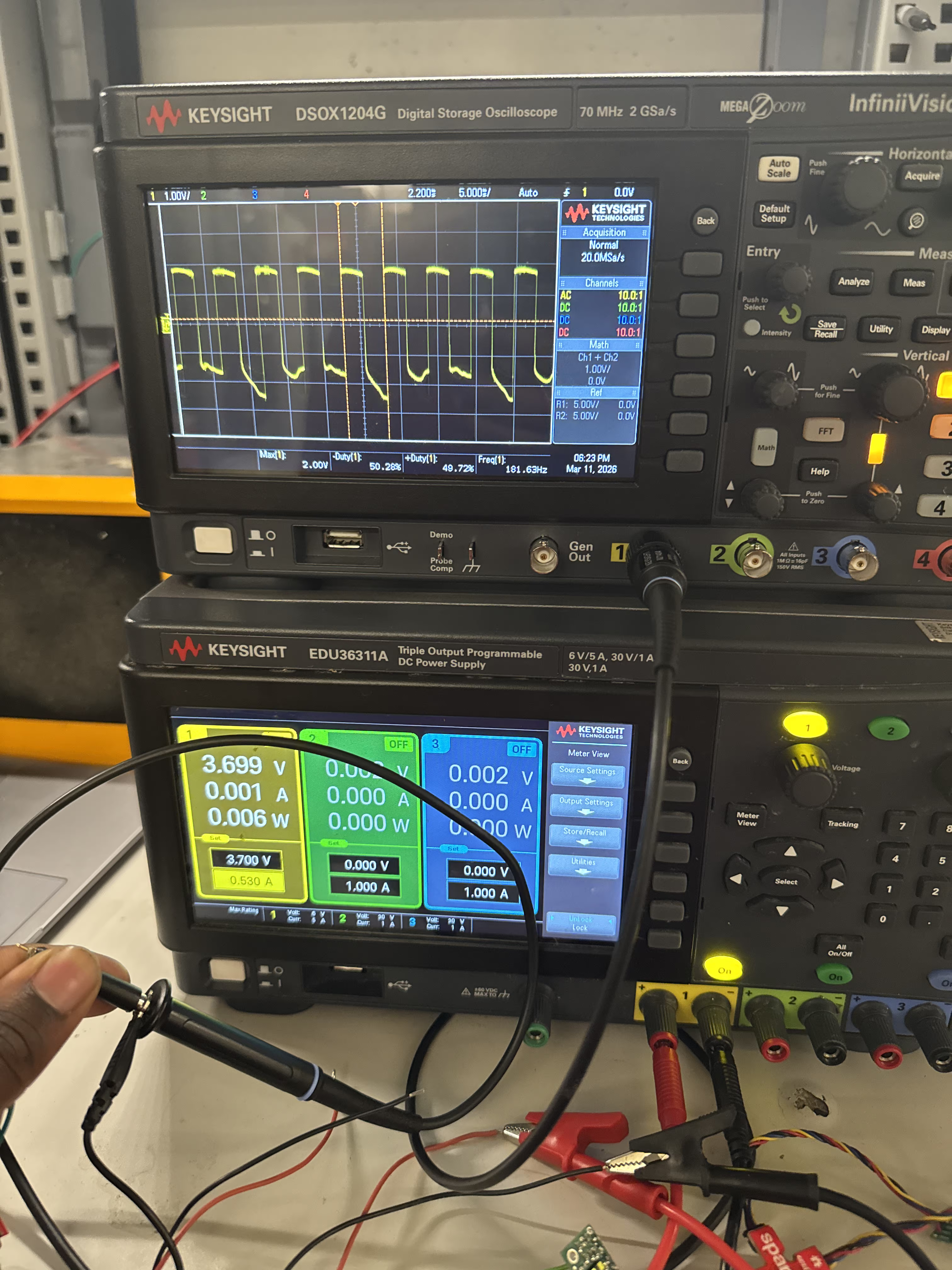
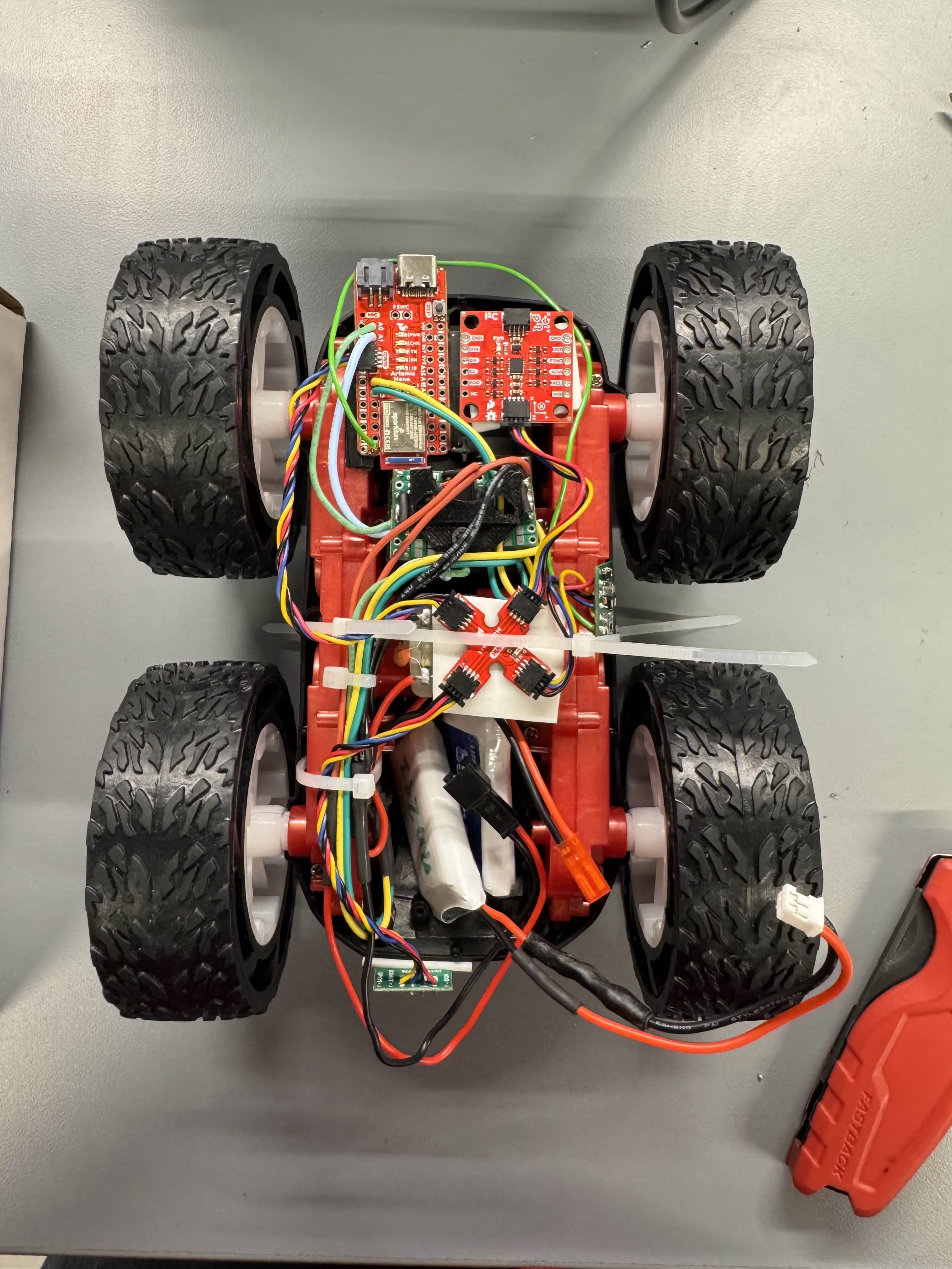
Image of Built Car
This is an image of the car once I added all my components and all of my components should be visible to see. I integrated my sensors as well and I'm working on a little bit of a better mounting system for my TOF sensors to make it stable.
Testing Robot Movement
Testing with Power Supply
Here is the movement of my robot with the power supply. As can be seen here the motor moves well in both directions and the limiting factor on speed currently is the current limit on the power supply.
Testing Both Motors with Battery
Here I created some code to test if both of the motors are able to be driven at the same time by the battery. I am a little concerned because I had to epoxy one of my wheels and I think the epoxy might have leaked and caused some extra friction but I cleaned that up to eliminate that to the best of my ability. I think that the epoxy is definetly messing up the movement, but my code below shows the different PWM values I needed to use.
//Set up Pins
const int DriveL1 = 1;
const int DriveL2 = 0;
const int DriveR1 = 2;
const int DriveR2 = 3;


  analogWrite(DriveL1, 40); //moving forward
  analogWrite(DriveL2, 0);
  analogWrite(DriveR1, 90); //moving forward
  analogWrite(DriveR2, 0);

  delay(3000);

  analogWrite(DriveL2, 40); //moving backward
  analogWrite(DriveL1, 0);
  analogWrite(DriveR2, 90); //moving backward
  analogWrite(DriveR1, 0);

  delay(3000);
Here is the video of how that looked.
The low speed on the left drive set (video persepective right) was one of the main reasons the wheel set on video perspective right was so slow.Lower PWM Limit
For my lower PWM limit tests I found that to make it go slow and on the flower I needed 92 on the right set of wheels and 50 on the left set of wheels. I think that this change is due to the epoxy adding different amount of friction on the left set which makes it just need more power.
For my turns, I found that I needed roughly 133 on my right to start movement in a turning direction, and I needed 140 on my left to start movement in the other turning direction.
Calibration
For the calibration I used my PWM script that turns on the motor for a set amount of time and changed the PWM values to make it go straight. I needed 95 on the left and 112 on the right to make it go straight for the required distance. The video below shows that. An interesting observation was that once it started moving the left wheels seemed to be more dominant so I had to increase the right wheels a lot to compensate, I think that this might be because with the epoxy the stationary friction is more but the moving friction is not bad. I also think this could be due to lower amounts of grip on the floor and this might need more testing to verify.
This is the code that I used:
void loop() {
  // put your main code here, to run repeatedly:
  analogWrite(DriveL1, 95); //moving forward
  analogWrite(DriveL2, 0);
  analogWrite(DriveR1, 112); //moving forward
  analogWrite(DriveR2, 0);

  delay(3000);

  analogWrite(DriveL2, 0); //moving none
  analogWrite(DriveL1, 0);
  analogWrite(DriveR2, 0); //moving none
  analogWrite(DriveR1, 0);

  while (1 == 1){
    delay(3000);
  }
}
Open Loop Control
For the open loop control I used the values that I found for the robot to go straight and I used those for the going straight sections. I did a similar thing with my turning values and set variables to make it easier for me to update these values as time progresses incase I find that different values work better than others.
Here the code that I used and my final results.
  analogWrite(DriveL1, StraightL); //moving forward
  analogWrite(DriveL2, 0);
  analogWrite(DriveR1, StraightR); //moving forward
  analogWrite(DriveR2, 0);

  delay(1000);

  analogWrite(DriveL1, 0); //moving forward
  analogWrite(DriveL2, StraightL);
  analogWrite(DriveR1, 0); //moving forward
  analogWrite(DriveR2, StraightR);

  delay(1200);

  analogWrite(DriveL1, TurnL+20); //moving forward
  analogWrite(DriveL2, 0);
  analogWrite(DriveR1, StraightR+10); //moving forward
  analogWrite(DriveR2, 0);

  delay(2000);

  analogWrite(DriveL1, 0); //moving forward
  analogWrite(DriveL2, 0);
  analogWrite(DriveR1, 0); //moving forward
  analogWrite(DriveR2, TurnR+20);

  delay(1000);

  analogWrite(DriveL1, 0); //moving forward
  analogWrite(DriveL2, 0);
  analogWrite(DriveR1, 0); //moving forward
  analogWrite(DriveR2, 0);

  while (1 == 1){
    delay(3000);
  }
Discussion
One interesting thing that I found is that if I flip the leads that were connected to the 50% duty cycle and 0% duty cycle pins incorrectly the scope trace becomes very weird and I'm not sure why this is but that was cool. The battery level also matters a lot for these tests which is something for me to note for the future.
Collaboration
I referenced Trevor Dales' website for confusion about wiring and the analogWrite section. I also used Google Gemini to help with making the code to plot the ToF results. I also worked with Aidan Chan to find pins for my board. Also reffered to Aidan Derocher's page for wiring help.