Prelab
Documentation Reading
Through reading the documentation I found that the ToF sensor is able to have 3 different ranges of detection which I thought was really cool, and each of the ranges give a different combination of how far it can measure and how accurate it can be in that range. I also learned that there is a calibration function to calibrate the ToF which would be really interesting to try out later. I also learned that the default I2C address is 0x52 through reading the data sheet.
Concurrent or Non-Concurrent
For my robot I am choosing to address both of the ToF sensors concurrently using different addresses because I believe that it will make the programming more streamlined and also make it easier to rapidly collect data across the sensors without need to switch on and off and intialize the sensors every time. I think that even though the data throughput might decrease a little bit due to having to have multiple sensors reading at similar times, but I think that the cycle time saved by not having to turn sensors on and off would make up for that and overall increase the amount of data that is able to be collected. I will do this in the beginning of my program by shutting down one of the sensors using the XSHUT pin and then assigning a new address to the other sensor, that will then allow me to selectivley turn the first sensor back on and then following just command the sensors individually with their different addresses.
Placement of the ToF Sensor
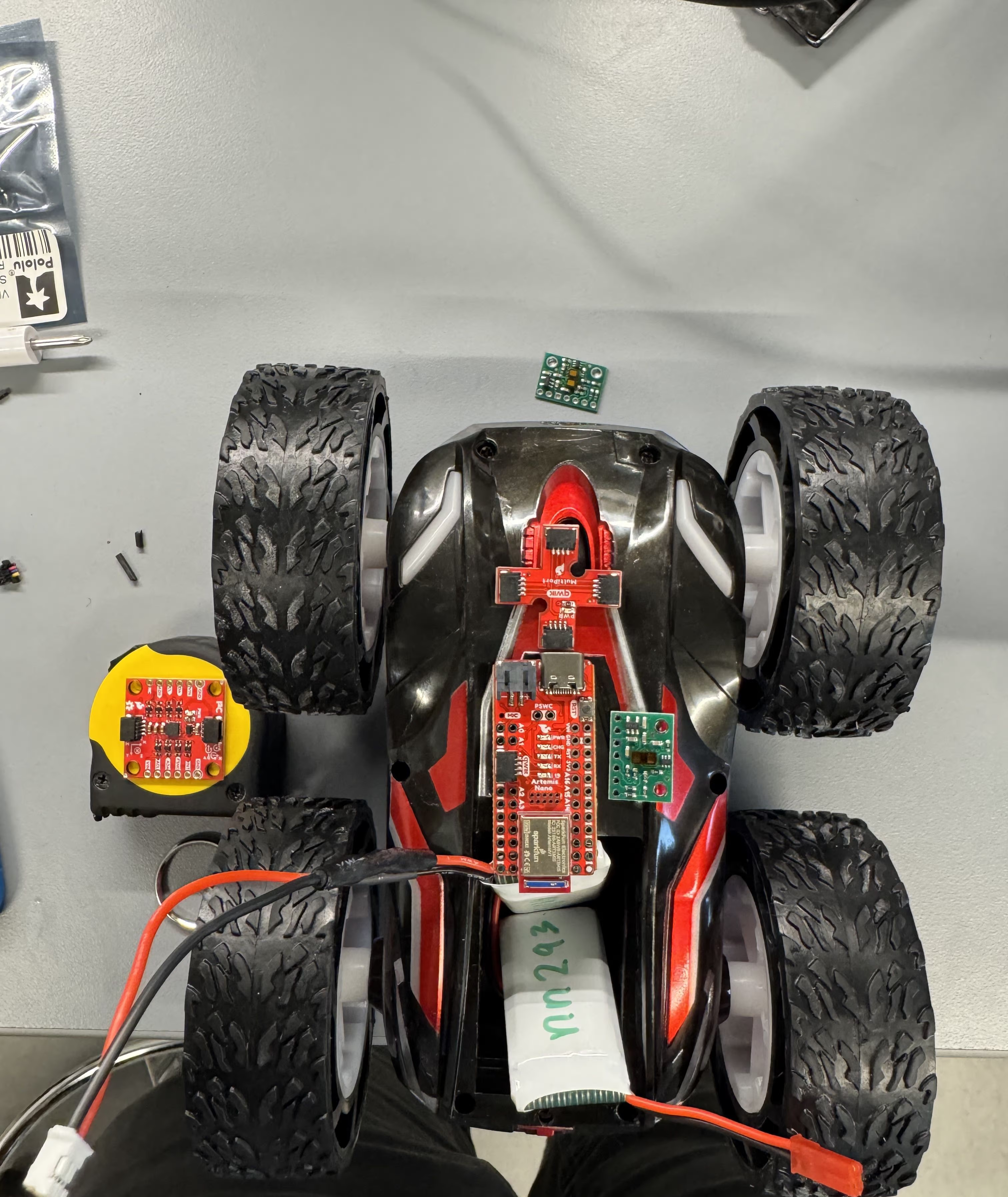
I chose to place one of my sensors in front of my car to avoid obstacles that my car will run into while driving straight and I also chose to place my other sensor on the side of my car to allow for avoidance of walls or for keeping a distance from a wall so that the robot wont drive into obstacles on the side. I also used a short wire on the side to allow for this and a long wire for the front. My vision of how I want to mount these components is shown here. This does mean that my car will miss obstacles that is on its left side and back.
Wiring
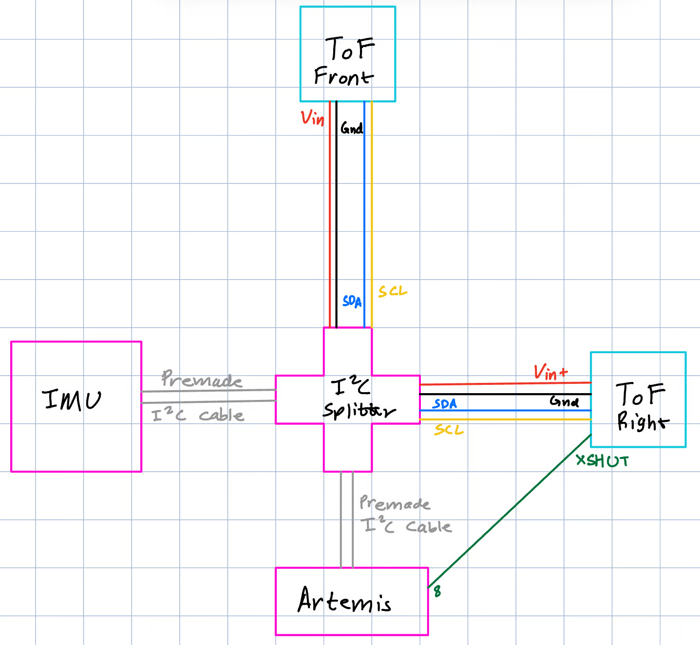
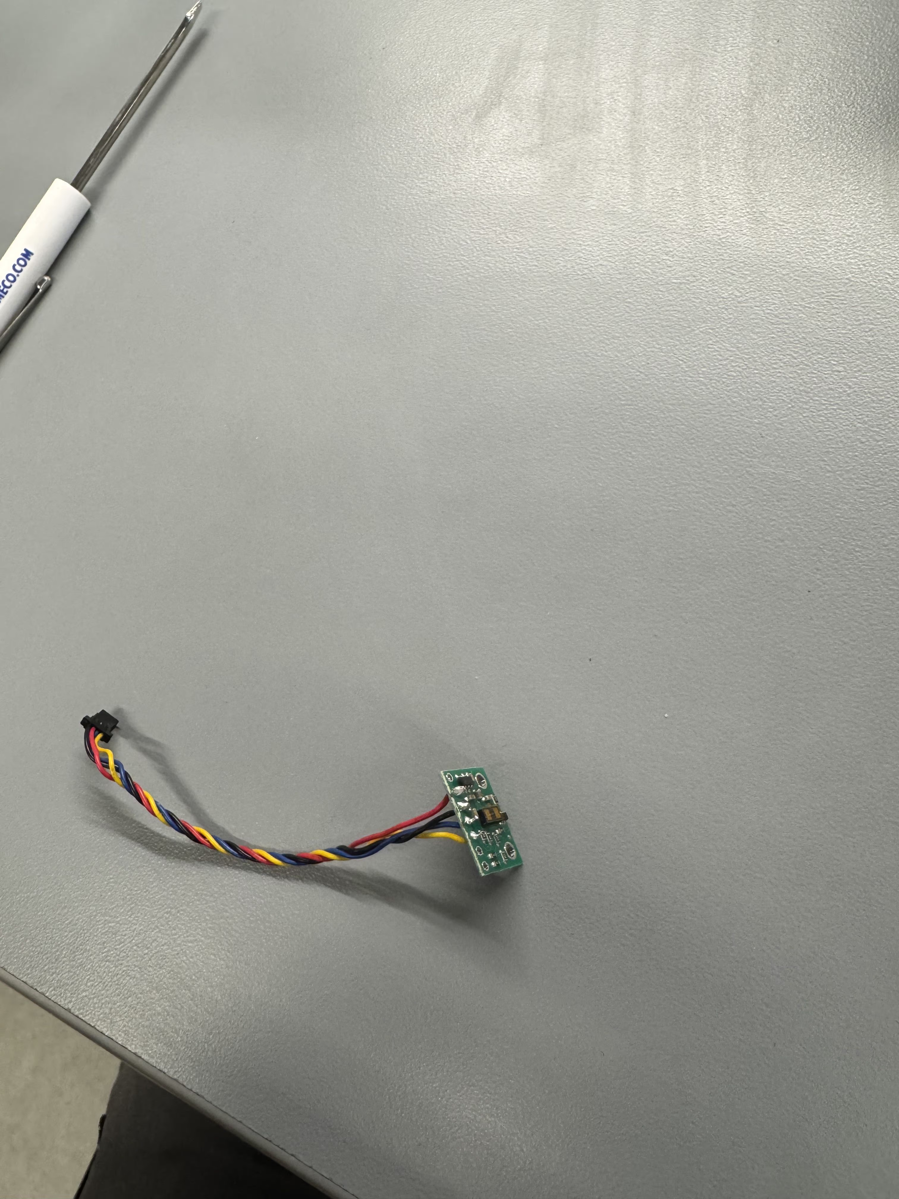
Since I chose to put a sensor in the front and the side I will be using the longer QWIIC wire to attach to the front ToF sensor and the short QWIIC wire to attach the side one since it only has to go a shorter distance. Using the QWIIC wire also allows the sensors to be detached incase there needs to be a physical disconnect to set up the different sensors and also allows for easier troubleshooting as well. The connection between the ToF sensor and the wire can be permenant for this reason and I soldered the wires through the back so that they will not interfere with attaching the sensor to the robot. I did not cut the wires short and preserved as much of the length as possible so that I could keep the flexibility of slightly changing position later if needed. My wiring diagram is below, and I followed the color convention of the QWIIC wire with the ToF sensor labelled pins.
Lab Tasks
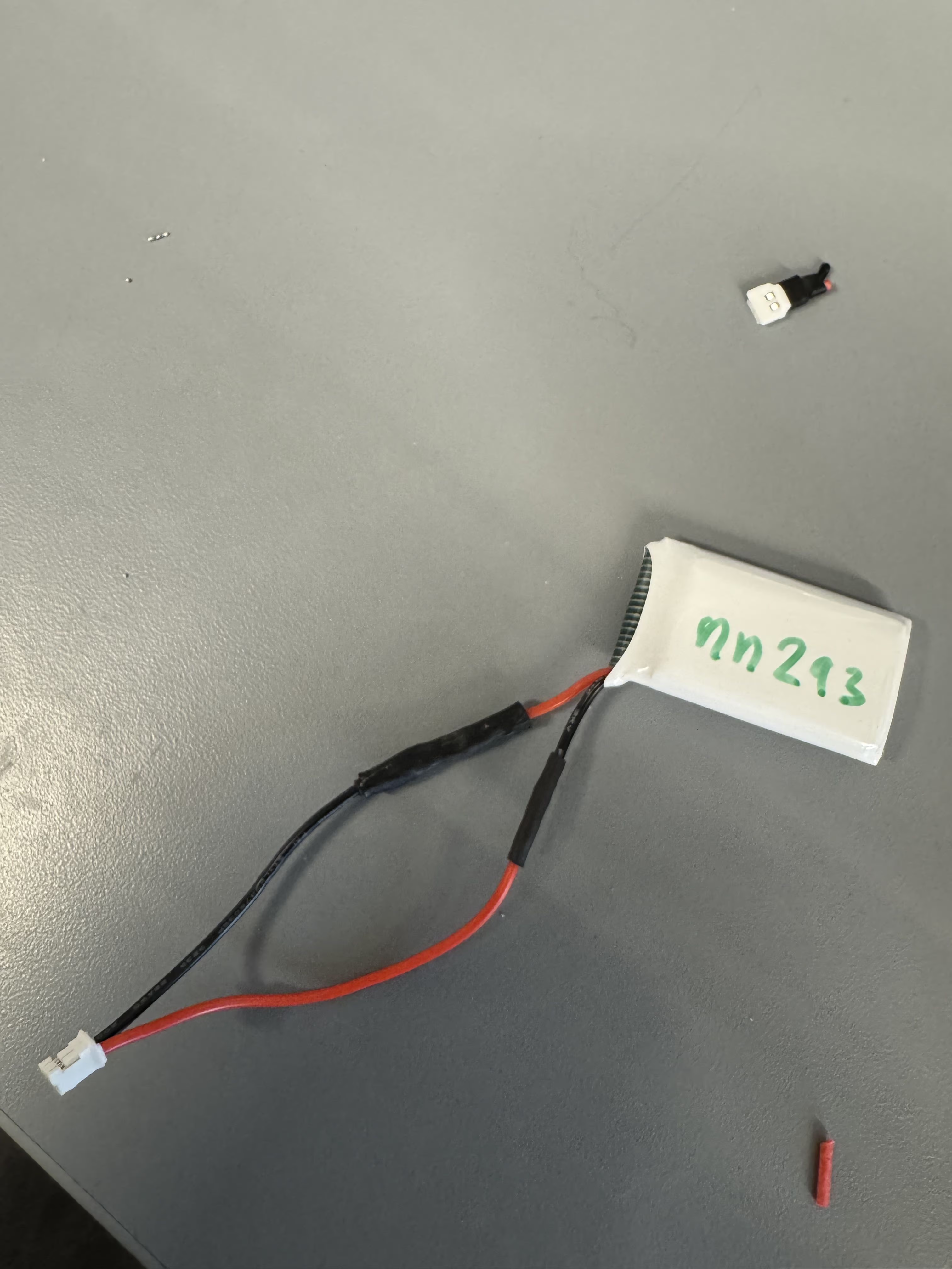
Soldering the Battery Connector
I soldered a new connector to the LiPO to allow for connection to the Artemis, picture of that connection is below.
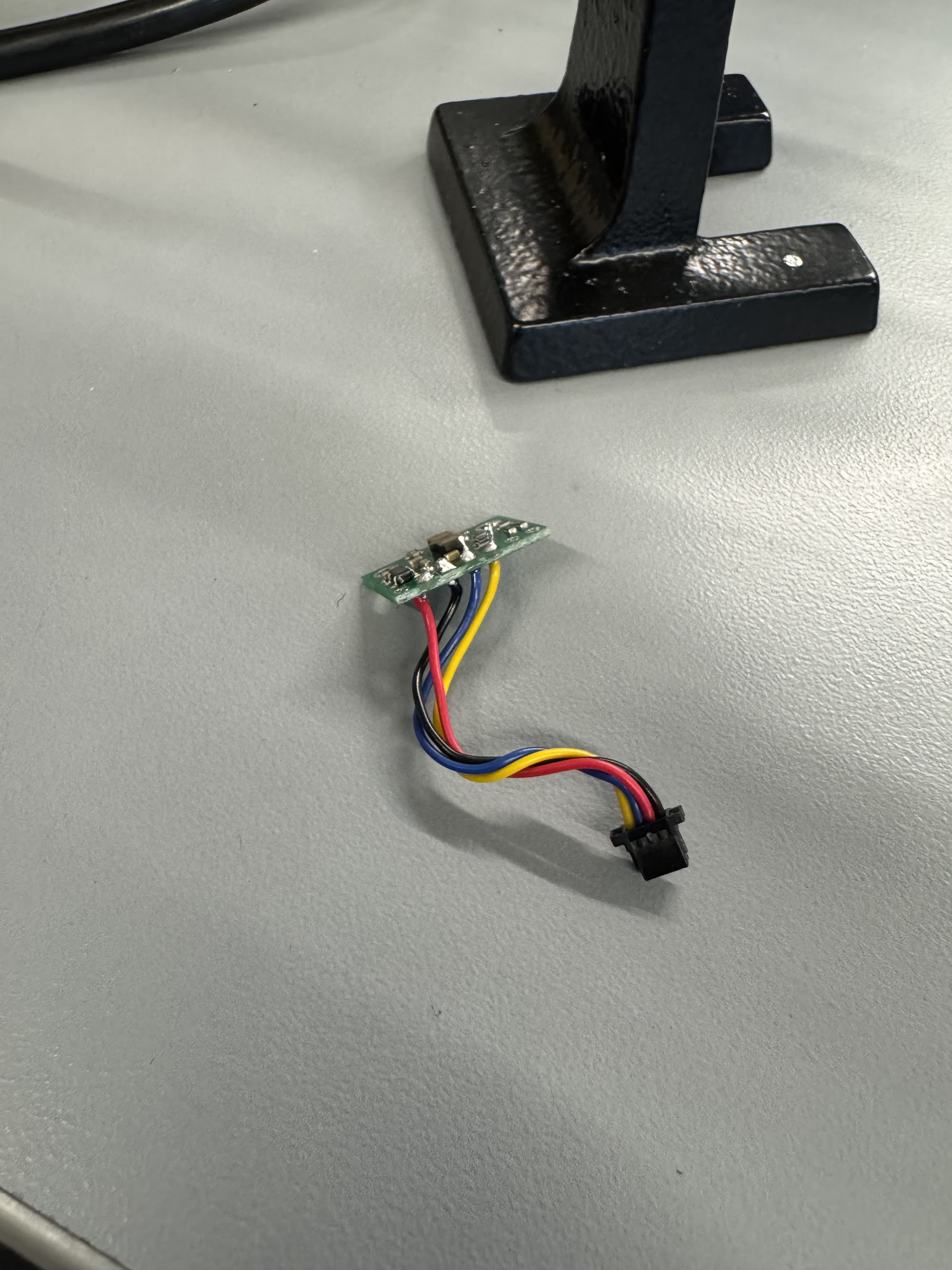
ToF Setup and Soldering
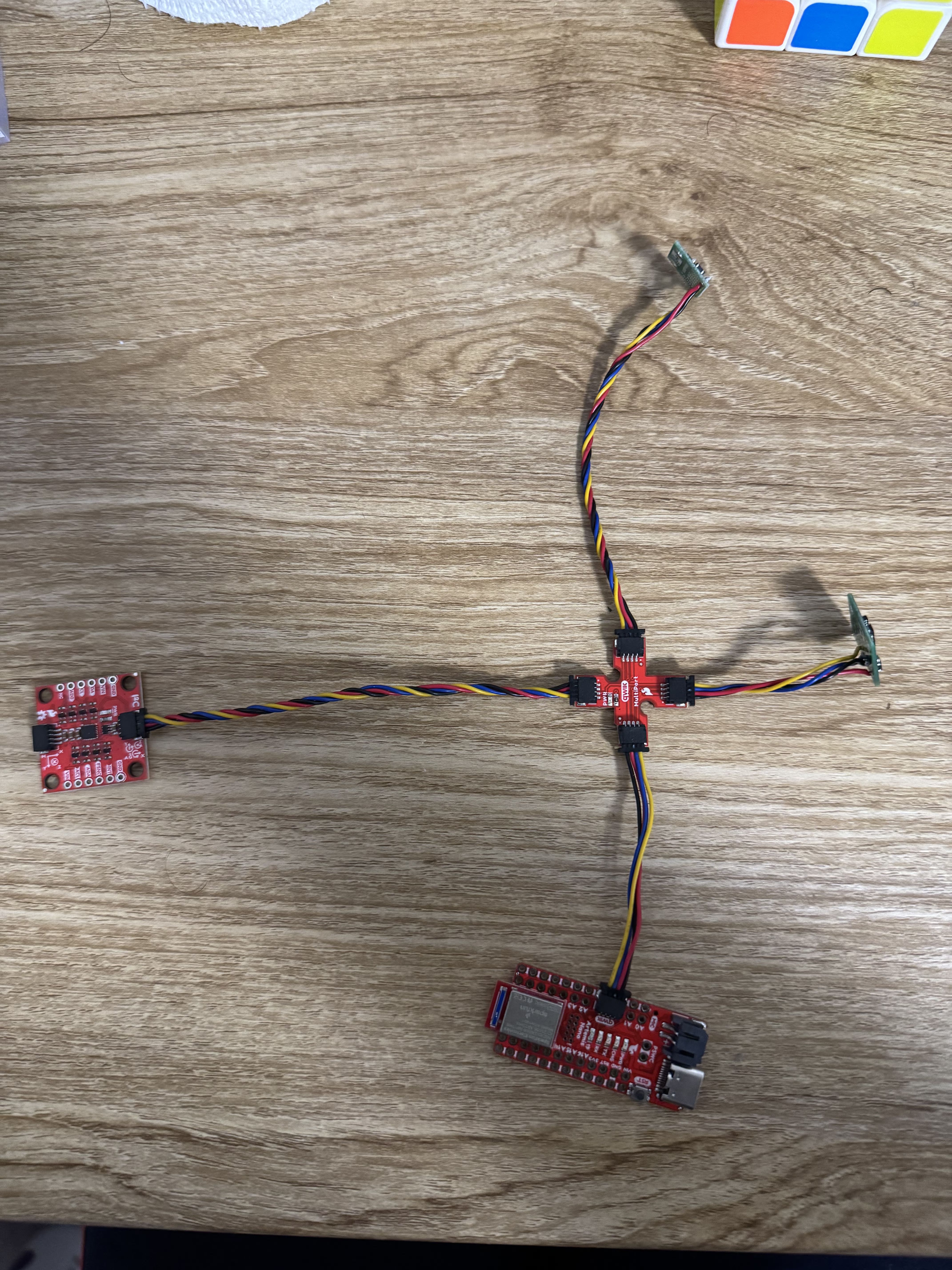
I downloaded the library, wired the breakout board, and also soldered the connectors to the ToF sensors based on my wiring diagram. Through the QWIIC documentation I found that the blue wire is for SDA and yellow is for SCL. Below are images of my completed sensors and wiring.
ToF I2C
To find and test the I2C address of the sensor I connected just one sensor to the Artemis and used the recommended Wire_I2C example to find the I2C address of the ToF sensor. I found that the address was 0x29. This is different than the 0x52 and I noted that 0x29 becomes 0010 1001 in 8 bit binary and 0x52 becomes 0101 0010. I also noticed that in the wire code the for loop to execute the serial print only activates if the address is under 127 which is a 7 bit number, so I believe that by default an I2C address is only supposed to be a 7 bit number such as what 0x29 is and the last bit is used for read or write designation as is explained in the data sheet, so since here we are reading from the sensor the I2C address is left shifted and a 0 is appended, which gives 0x52 in binary since 0010 1001 (0x29) left-shifted is 0101 0010 (0x52) which is what is detailed in the ToF manual. Thus this information corroborates the manual's address.

Sensor Mode
Here the main modes I considered were the Short and Long modes since Long and Middle modes were very similar in terms of performance in different lighting and only had a 1 meter range difference. The data sheet and manual did not have much description between the Short and Long modes except for showing its performance in dark and light as well as distance. I saw that the Long mode had a very high sensitivity to light and especially bright light made it lose its ranging capabilities really fast and decreased its maximum range to half of the range of the short mode in the bright light environment, essentially nullifying the biggest pro of the Long mode which was high range. Since our lab is pretty brightly lit I think that the Short mode will give me the best measurements and most repeatable measurments regardless of environmental conditions so I will be using the Short mode. I also feel the Short mode range of 1.3 meters will be adequate to navigate around any obstacles faced by the robot as well.
Sensor Measurement Analysis
I used the sensor sample code to get a number of measurements to test the sensor.
Ranging
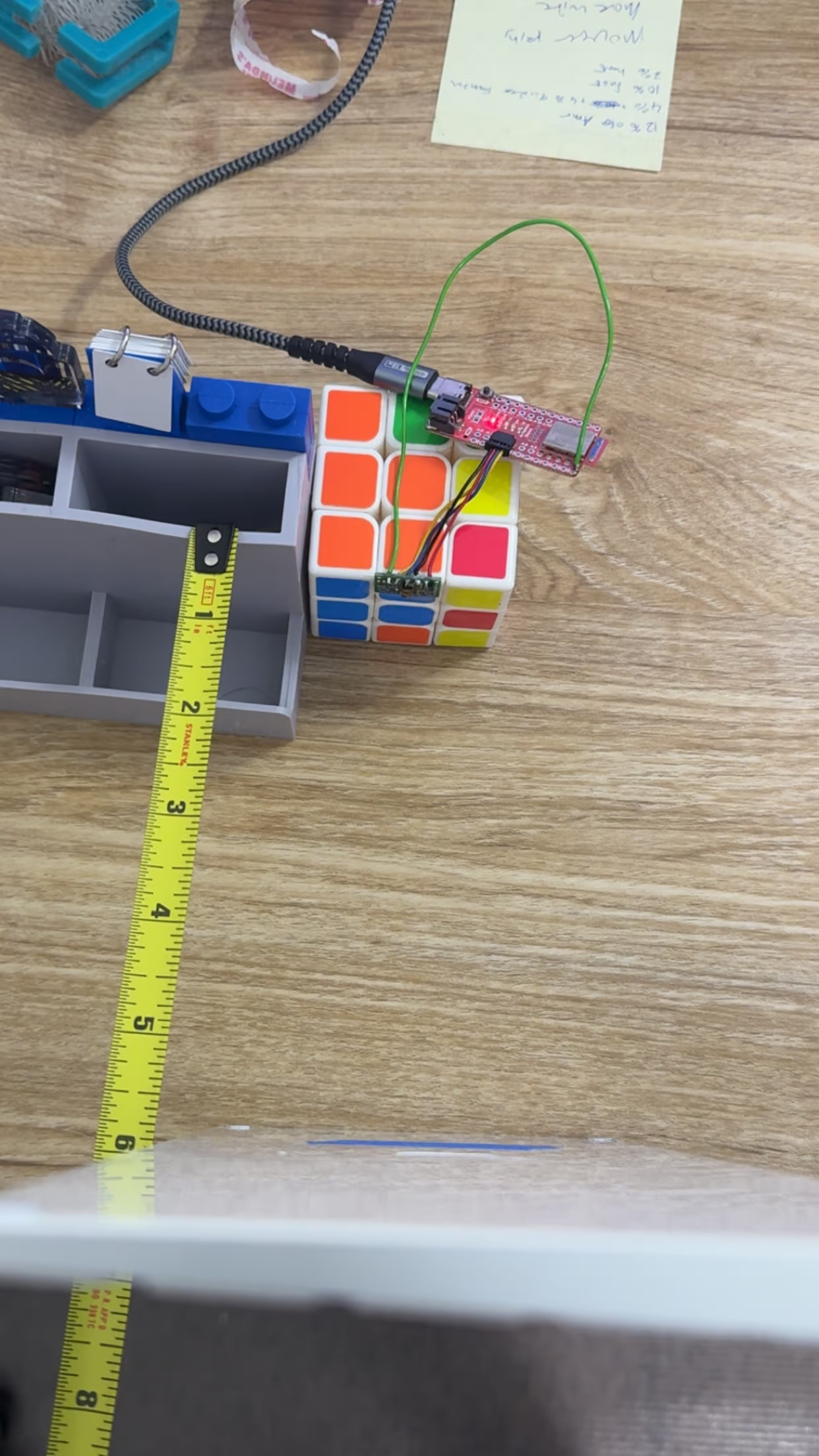
To test ranging I set up a testing set up as below and screen recorded as I moved the flat keyboard up in 6 inch increments (I took the protective film off before doing my final test). My setup wasn't perfectly precise but it was good enough to get a rough estimate of accuracy and I found that within the 4 foot range the sensor is very accurate in a evenly bright lit area. Within 2 feet the accuracy was to the 0.01 of a foot pretty much but after the 2 feet range it dropped to within 0.05 foot and beyond 4 feet it was only really accurate to the 0.1 foot which is still pretty good but something to take note off. Setup and video of the results below, jump in distances in the video is the 6 inch move.
Accuracy and Repeatability
I used my setup to accurately measure 6 inches and left my sensor to keep reading and I copied 150 of the measurement results in inches into python to plot it using matplotlib and below is my data. I had to change my output in the arduino script to only output the inch value and no text to make it easy to parse.
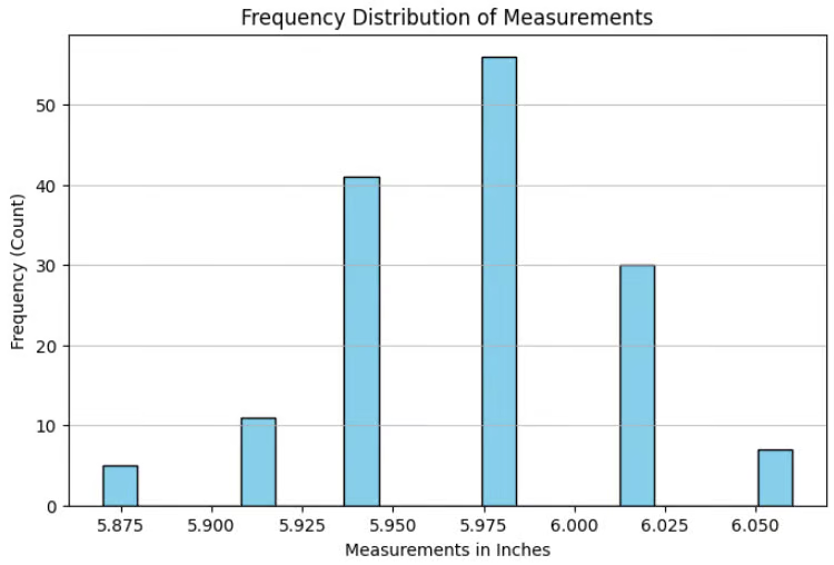 Based on the plot I found that the repeatability is generally within 0.1 of an inch even if the object is not moving at all and generally the measurements are pretty close to the expected measurement. I also found that the sensor reads in bins of 0.04 inches and that is something to keep in mind if I see repeated measurements in the future as well. I think that this is due to the conversion between the millimeter reading to the inches that are being displayed.
Ranging Time
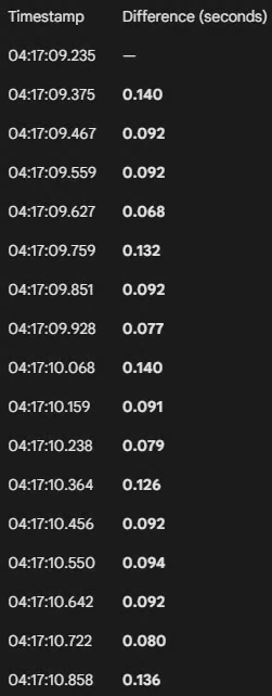
Since the data is only collected when the sensor is ready I can use the time stamps of the serial output to find the time. I found through looking through the video that the rough time is around 101.4 milliseconds between each of the times.
This is the time information that was calculated.
Dealing with Double Sensor Problem
Based on the Artemis pinouts, I found that I need a GPIO pin that can control high and low to operate the XSHUT so that I can decide which sensor to assign a different address too, and chose pin 8 since it didn't have a secondary function and was not an ADC either. I decided to solder the XSHUT pin on the right sensor since it has a shorter cable thus shorter run of wire needed.
Here is the code I used to intialize the sensors seperately by assigning a new I2C address to one of them and initializing 2 instances of the distance sensor. The code to read it was based on the example code for sensor reading and I collected the data seperately and displayed them seperately.
  Wire.begin();

  Serial.begin(115200);
  Serial.println("VL53L1X Qwiic Test");

  digitalWrite(XSHUT_PIN, LOW); //shutting down the side sensor
  distanceSensor1.init(); //starting the first sensor
  distanceSensor1.setI2CAddress(0xf5);

  if (distanceSensor1.begin() == 0){ //0 means it intialized well
    Serial.println("Started Sensor 1");
  }
  distanceSensor1.setDistanceModeShort();

  digitalWrite(XSHUT_PIN, HIGH); //start the side sensor again
  if (distanceSensor2.begin() == 0){ //0 means it intialized well
    Serial.println("Started Sensor 2");
  }
  distanceSensor2.setDistanceModeShort();
Here is a video of the 2 sensor readings working.
Measurement Timing
Here I printed out the millisecond time as ranging continued and I checked if the sensors had data ready on every loop and printed out when they had data ready. A video of the behavior is below. In the video I can see that the time is printed out much faster and I can see that the loop executes in 5 milliseconds because that is the difference between each of the times that is outputted, between each output of each distance sensor I found that there is 56 milliseconds of difference and that means that the polling of the sensor is around 10 times slower than the execution time of the loop. I think that the current limiting factor is polling the sensor and also how fast the sensor can collect data is what is slowing down how long it takes for new data to be printed.
Here is the code I used to make this happen.
distanceSensor1.startRanging(); //write configuration bytes to initiate measurement
  distanceSensor2.startRanging(); //write configuration bytes to initiate measurement

  Serial.print(String(millis()));
  if (distanceSensor1.checkForDataReady()){
    int distance1 = distanceSensor1.getDistance(); //get the result of the measurement from the sensor

    distanceSensor1.clearInterrupt();
    distanceSensor1.stopRanging();


    Serial.print("Distance1(mm): ");
    Serial.print(distance1);

  }

  if(distanceSensor2.checkForDataReady()){
    int distance2 = distanceSensor2.getDistance(); //get the result of the measurement from the sensor
    distanceSensor2.clearInterrupt();
    distanceSensor2.stopRanging();

    Serial.print(" Distance2(mm): ");
    Serial.print(distance2);
  }

  Serial.println();
Sending Data Over Bluetooth
Here to execute this I will be using the code that I made for temperature and time in lab 1 and adding new arrays to store the data from the distance sensors and then send that over to the python script.
case GET_IMU_TOF: {
            int num = 0;
            long startingTime = millis();
            float pitch = 0;
            float roll = 0;
            float distance1 = 0;
            float distance2 = 0;
            memset(timeArray, 0, arraySize); /*intializing to 0 incase ran before to prevent excess printing*/

            distanceSensor1.startRanging(); //write configuration bytes to initiate measurement
            distanceSensor2.startRanging();

            while ((millis()-startingTime < 5000) && (num < arraySize)){ //doing till 5 seconds or the array is filled
                timeArray[num] = (double) millis();
                if (myICM.dataReady()){
                    myICM.getAGMT();


                    pitch = atan2(myICM.accX(), myICM.accZ()) * 180 / M_PI;
                    roll  = atan2(myICM.accY(), myICM.accZ()) * 180 / M_PI;

                    pitch = (1.0285 * pitch);
                    roll = (1.0285 * roll);

                    rollArray[num] = roll;
                    pitchArray[num]= pitch;
                }

                if(distanceSensor1.checkForDataReady()){
                    distance1 = distanceSensor1.getDistance();
                    distanceSensor1.clearInterrupt();
                    distance1Array[num] = distance1;
                }

                if(distanceSensor2.checkForDataReady()){
                    distance2 = distanceSensor2.getDistance();
                    distanceSensor2.clearInterrupt();
                    distance2Array[num] = distance2;
                }

                delay(20); //delay to ensure array not filled to fast and not repeated values
                num++;
            }

            distanceSensor1.stopRanging(); //write configuration bytes to stop measurement
            distanceSensor2.stopRanging();

            num = 0;//resetting the number count

            while ((num < arraySize) && (timeArray[num] != 0)){ //doing this loop for 5 seconds for this test
                //using similar string output structure to millis_loop
                tx_estring_value.clear();
                tx_estring_value.append(num); //to keep count
                tx_estring_value.append(" T|R|P|D1|D2: ");
                tx_estring_value.append(timeArray[num]);
                tx_estring_value.append(" ");
                tx_estring_value.append(rollArray[num]);
                tx_estring_value.append(" ");
                tx_estring_value.append(pitchArray[num]);
                tx_estring_value.append(" ");
                tx_estring_value.append(distance1Array[num]);
                tx_estring_value.append(" ");
                tx_estring_value.append(distance2Array[num]);
                tx_characteristic_string.writeValue(tx_estring_value.c_str());
                num++;
            }
            break;
        }
This is my updated notification handler below.
def notif_handler(uuid, byteArray):
    rec_string = ble.bytearray_to_string(byteArray)
    strArray = rec_string.split(" ") #using space as a delimeter since my output from arduino is T: nnnnn and thus space will split it perfectly

    #using this if statement so that if the recieved string is not the time string it prints the whole thing instead of just the millis
    if strArray[0] == "T:":
        print(strArray[1])
    elif strArray[1] == "Time|Temp:":
        print(strArray[0] + "|Time: " + strArray[2] + " |Temp: " + strArray[3])
    elif strArray[1] == "T|R|P:":
        print(strArray[0] + "|Time: " + strArray[2] + " |Roll: " + strArray[3]+ " |Pitch: " + strArray[4])
    elif strArray[1] == "T|R|P|D1|D2:":
        print(strArray[0] + "|Time: " + strArray[2] + " |Roll: " + strArray[3]+ " |Pitch: " + strArray[4] + " |Distance1: " + strArray[5]+ " |Distance2: " + strArray[6])
        add = [float(strArray[0]), float(strArray[2]), float(strArray[3]), float(strArray[4]), float(strArray[5]), float(strArray[6])]
        IMUTOF.append(add)
    else:
        print(rec_string)
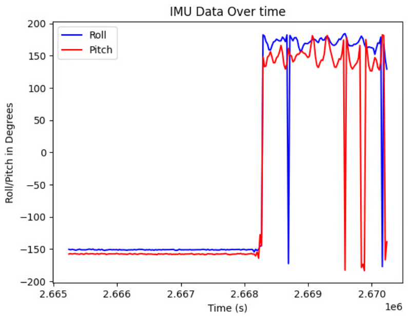
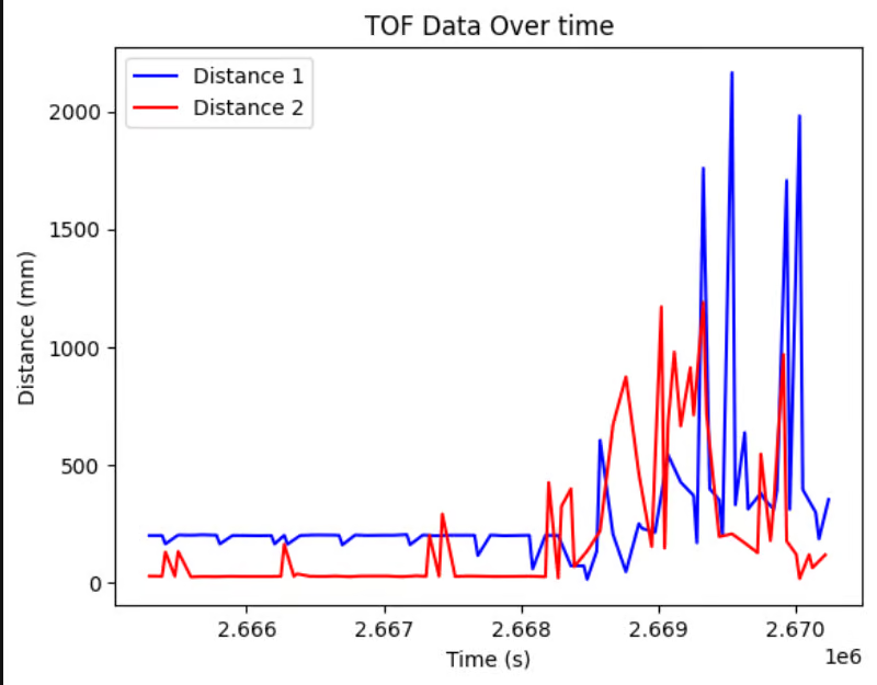
These are the graphs that I made with some of my IMU data and my TOF data.
Discussion
One great learning was that taking the protective film off really does improve the measurements lol, and after taking the film off my measurements improved a lot.
Collaboration
I referenced Trevor Dales and Lucca Correia's websites for issues I faced in Lab 3, mainly with figuring out how to control 2 different ToF sensors at the same time. I also used Google Gemini to help with making the code to plot the ToF results, and also for finding the difference in time between the time stamps, and also for figuring out how to efficienlty use python lists. I also worked with Aidan to troubleshoot to my arduino code to transmit TOF and IMU data.