Prelab
For the prelab I read through the overview given about the IMU and skimmed through the datasheet as well. My main takeaways were that the IMU is full featured and has the ability to read in different scale ranges and that it has a gyroscope, an accelerometer, and a magnetometer. It was also cool to learn about the different ways that each sensor finds its reading, especially that the gyroscope works by using the coriolis effect and capactiance changes.
Lab Tasks
Prep RC Car
I started charging my battery, and the one that came with my car was puffy so I had that switched out for a different not puffy one.
Setting up the IMU
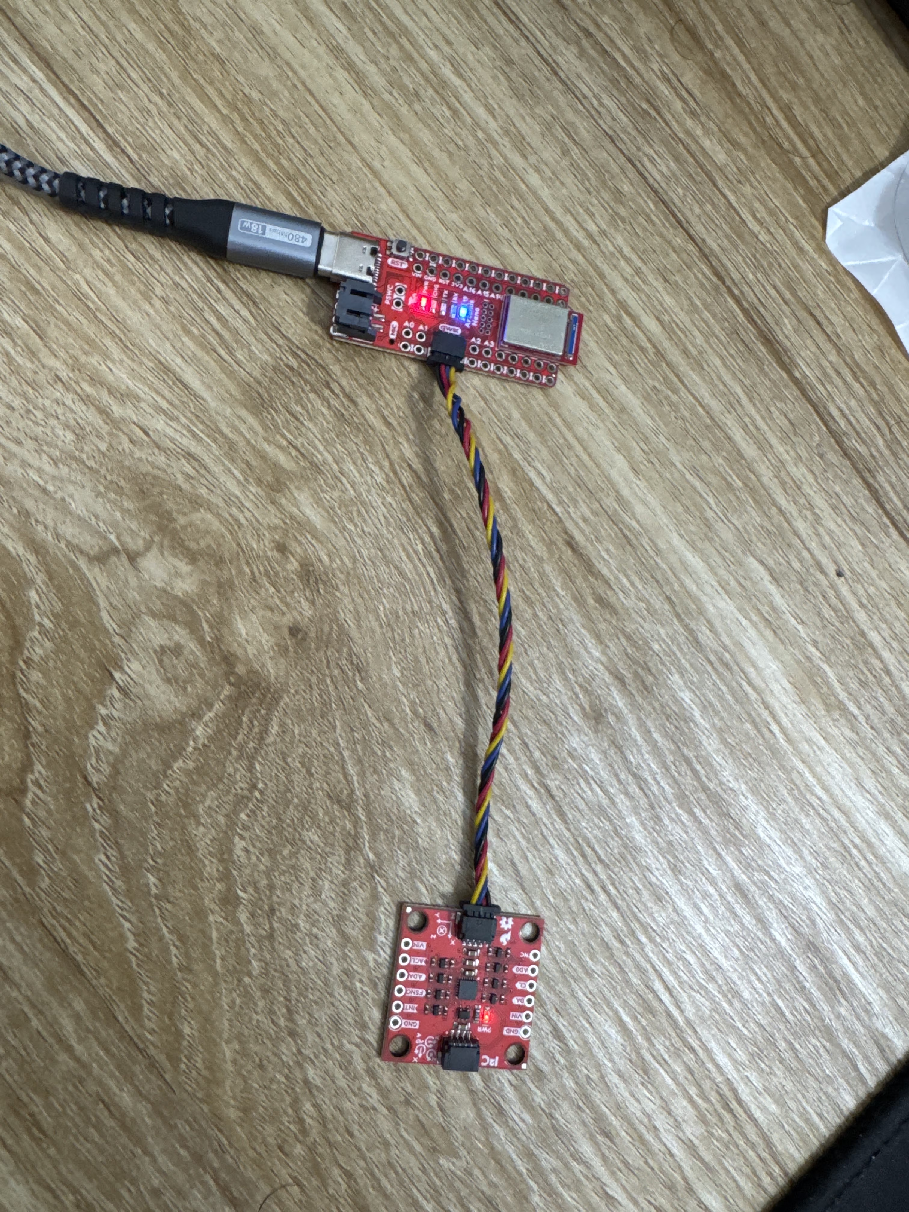
Here is a picture of my IMU connected to my Artemis.
I then ran the example IMU set up code and here is a video showing that the values are changing as I move the board around.
ADO Discussion
In the comments in the example code it describes that AD0 is the value of the last bit of the I2C address and by default without the ADR pins jumpered on the board it is 1 and when they are jumpered it becomes 0. This would be useful to change if there are multiple I2C devices that share the same address and if there are 2 IMU's or something like that it would be very useful for both of them to have different I2C addresses so they can be accurately addressed.
Accelerometer and Gyroscope
I mounted my IMU to a little tape measure using double sided tape to act as a weight to make it easier to handle.
When at rest facing up the gyroscope records pretty much 0 in each direction and the acclerometer detects 0 G in the x and y but has roughly 1 G in the z direction (image below). I also found that if I had it resting with y or x pointing up/down the respective axes would show 1 G roughly of acceleration.

I then kept it on the table and moved it in the x and y directions and when I moved it in the y direction as indicated on the IMU board I saw a sharp increase in the accelerometer y data and similarly in the x direction as well. Below is a screenshot of one such movement on the table in the y direction.

I tried dropping the IMU but due to gravity being the same I didn't see any additional change in the accelerometer data until when it hit the soft surface I had below it which in that moment it had 0 acceleration in the drop direction.
With the X axis pointing to the right when I flip the IMU from flat on the table to upright I can see a change in the X direction of the gyroscope and the others dont change. I also noticed the same behavior when I did it for the Y axis side as well. The flip also causes the accelerometer data to change because of the acceleration changes and all 3 axes of accelerometer data changed. Below is an image of the data when I flipped in the X.

While resting on the table and rotating I was able to make the Z axis gyroscope change as well, and in this configuration the change to the X and Y acceleration was also very clear. Below is an image of the change in Z gyroscope.

A big takeaway for me from here is that it is possible to accelerate the board without any or with very minimal change to the gyroscope (straight line acceleration) but the converse is not true and even for slight gyroscopic moves there is always an acceleration associated with it.
Blink and IMU Setup
To set up the IMU as part of the arduino_ble.ino file I used the set up commands that were used as part of the IMU example but editted them to only the I2C sections since that's all we are using in this lab. I also referenced the arduino default blink example to get the commands needed to make the LED blink and I set a 1000 ms delay between led on and off to allow for a slow blink to show that board is fully set up. I also included the library for the IMU, ICM_20948.h, as part of the arduino_ble file.
Below is the static code I needed to add.
//IMU static values needed
#define WIRE_PORT Wire
#define SERIAL_PORT Serial
// On the SparkFun 9DoF IMU breakout the default is 1, and when the ADR jumper is closed the value becomes 0
#define AD0_VAL 1
ICM_20948_I2C myICM;
Below is the code that I added to my setup() function.
//setting up the IMU with code from IMU example
    WIRE_PORT.begin();
    WIRE_PORT.setClock(400000);
    bool initialized = false;
    while (!initialized){
        myICM.begin(WIRE_PORT, AD0_VAL); //we are only using I2C
        Serial.print("Initialization of the sensor returned: ");
        Serial.println(myICM.statusString());

        if (myICM.status != ICM_20948_Stat_Ok){
            Serial.println("Trying again...");
            delay(500);
        }
        else{
            initialized = true;
        }
    }

    // 3 LED blink to show that the board is fully set up
    pinMode(LED_BUILTIN, OUTPUT);
    digitalWrite(LED_BUILTIN, HIGH);  // turn the LED on (HIGH is the voltage level)
    delay(1000);                      // wait for a second
    digitalWrite(LED_BUILTIN, LOW);   // turn the LED off by making the voltage LOW
    delay(1000);
    digitalWrite(LED_BUILTIN, HIGH);  // turn the LED on (HIGH is the voltage level)
    delay(1000);                      // wait for a second
    digitalWrite(LED_BUILTIN, LOW);   // turn the LED off by making the voltage LOW
    delay(1000);
    digitalWrite(LED_BUILTIN, HIGH);  // turn the LED on (HIGH is the voltage level)
    delay(1000);                      // wait for a second
    digitalWrite(LED_BUILTIN, LOW);   // turn the LED off by making the voltage LOW
    delay(1000);
Accelerometer
Equations to Convert Pitch and Roll
From the lecture I found that the equation for converting is simply just the atan of x and z for pitch and roll is atan2 of y and z. Using this I implemented the following code in the example IMU code to show the pitch and roll of the IMU. I also had to include the math.h library to make this work.
Here is my conversion code that I added.
 pitch = atan2(myICM.accX(), myICM.accZ()) * 180 / M_PI;
    roll  = atan2(myICM.accY(), myICM.accZ()) * 180 / M_PI;

    Serial.print("Pitch: ");
    Serial.print(pitch);
    Serial.print(" ,Roll ");
    Serial.println(roll);
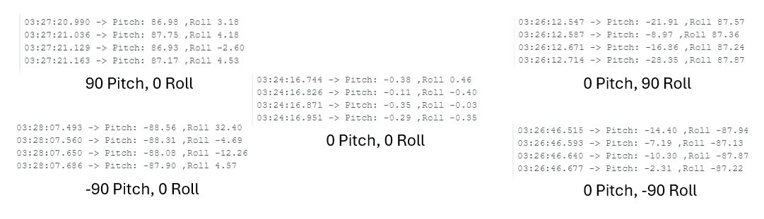
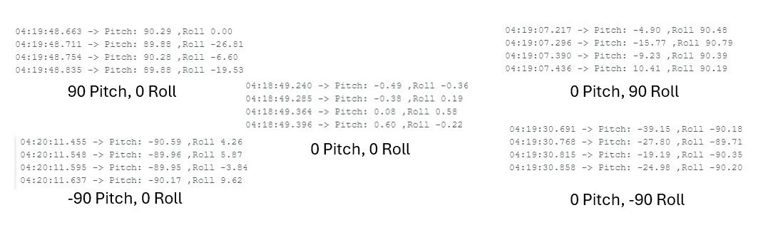
Here is a video showing the output as I tilted my IMU to the various pitch and roll amounts. I also attached my IMU to a rubiks cube to get a more accurate angle measurement and then measured both 90 and -90 degrees for each axes and I found that each measurement was around 3 degrees off (roughly 3.33% error) so to make that more accurate I did a 2 point calibration. To find the conversion factor I used the total range expected over total range measured and found a 1.0285 multiplicative conversion factor for both roll and pitch.
Here is what it it was for -90,0,90 degrees pitch and roll respectively before the calibration.
After the calibration this was the result. (this is a lot closer to expected)
Graphing Function
To make graphing the roll and pitch data easier later I chose to use a function similar to the save data and send in a big bunch function that we made for temperature and time in lab 1. Here I added a roll and pitch column instead of temperature and still used time, I also set up a condition in my notification handler to parse this data and made a seperate function to store the roll, pitch, and time in an array.
Here is my arduino code.
case GET_ROLL_PITCH_ARR: {
            int num = 0;
            long startingTime = millis();
            float pitch = 0;
            float roll = 0;
            memset(timeArray, 0, arraySize); /*intializing to 0 incase ran before to prevent excess printing*/


            while ((millis()-startingTime < 5000) && (num < arraySize) && myICM.dataReady()){ //doing till 5 seconds or the array is filled
                myICM.getAGMT();
                timeArray[num] = (double) millis();

                pitch = atan2(myICM.accX(), myICM.accZ()) * 180 / M_PI;
                roll  = atan2(myICM.accY(), myICM.accZ()) * 180 / M_PI;

                pitch = (1.0285 * pitch);
                roll = (1.0285 * roll);

                rollArray[num] = roll;
                pitchArray[num]= pitch;

                delay(35); //delay to ensure array not filled to fast and not repeated values
                num++;
            }

            num = 0;//resetting the number count

            while ((num < arraySize) && (timeArray[num] != 0)){ //doing this loop for 5 seconds for this test
                //using similar string output structure to millis_loop
                tx_estring_value.clear();
                tx_estring_value.append(num); //to keep count
                tx_estring_value.append(" T|R|P: ");
                tx_estring_value.append(timeArray[num]);
                tx_estring_value.append(" ");
                tx_estring_value.append(rollArray[num]);
                tx_estring_value.append(" ");
                tx_estring_value.append(pitchArray[num]);
                tx_characteristic_string.writeValue(tx_estring_value.c_str());
                num++;
            }
            break;
        }
Here is my python code for my array storing.
Stunt Recording
I recorded a few videos of my robot in action and did a few stunts. I broke off one of my wheels sadly but with a bit of epoxy I was able to put it back on fully. I can see that the robot travels very rapidly and I hope to emulate that with my system in the future as well. I also saw it was easiest to do flips and full rotations or drifts when moving with the robot.
Discussion
It was really cool to play around with the car and I was amazed how fast the car could move as well and I'm super pumped to see how we can control it ourselves.
Collaboration
I referenced Trevor Dales and Lucca Correia's websites for issues I faced in Lab 2. I used Google Gemini to help me understand compile errors.